Dense Wavelength Division Multiplexing (DWDM) is an innovation that enables multiple optical carriers to transmit in parallel over a single optical fiber. DWDM devices combine the outputs of multiple optical transmitters and transmit them over a single optical fiber. At the receiving end, another DWDM device separates the combined optical signals and delivers each channel to optical receivers. Only a single fiber (for each transmission direction) is used between DWDM devices. How does a DWDM system work, and what components are required? Read on to find answers in this article.
Typically, components used in DWDM systems include optical transmitters and receivers, DWDM multiplexers/demultiplexers, Optical Add-Drop Multiplexers (OADM), optical amplifiers, and wavelength converters (transponders). Let's delve into each of these devices individually.
Transmitters are referred to as DWDM components as they provide the source signal which is then multiplexed. The characteristics of optical transmitters used in DWDM systems are crucial for system design. The characteristics of optical transmitters used in DWDM systems are essential for accurate wavelength operation, without channel distortion or interference. Multiple separate lasers are commonly used to create individual channels in a DWDM system, each operating at a slightly different wavelength.
DWDM Mux (Multiplexer) combines multiple wavelengths created by multiple transmitters and running on separate fibers. The output signal from the multiplexer is referred to as a composite signal. At the receiving end, a DeMux (Demultiplexer) separates each individual wavelength of the composite signal onto separate fibers. Each fiber delivers the demultiplexed wavelength to as many optical receivers as possible. Typically, Mux and DeMux components are housed together. Optical multiplexers/demultiplexers can be passive, as signals are optically multiplexed and demultiplexed, eliminating the need for external power sources.
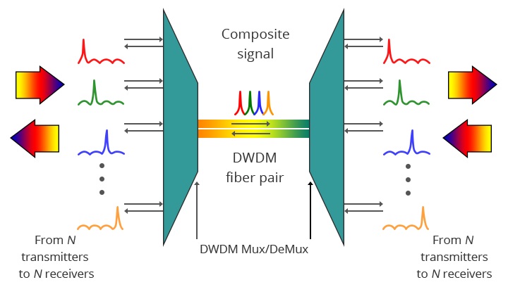
The diagram above illustrates bidirectional DWDM operation. N different wavelengths of optical pulses carried by N different fibers are combined by the DWDM Mux. N signals are multiplexed onto a pair of fibers. The DWDM Demux receives the composite signal and separates each component signal from the N wavelengths, passing each signal to the fiber. The arrows for transmit and receive signals represent client devices. This requires a pair of fibers, one for transmission and one for reception.
OADM is typically a device in WDM systems used to multiplex and route different fiber channels into and out of a Single-Mode Fiber (SMF). It is used to add/drop one or more CWDM/DWDM channel(s) optically to/from several fibers, enabling the addition or dropping of single or multiple wavelengths from a fully multiplexed optical signal. This allows intermediate locations between remote sites to access conventional point-to-point fiber segments connecting them. Un-dropped wavelengths will pass through the OADM and continue to the remote site. Additional selected wavelengths can be added or dropped through successive OADMs if needed.
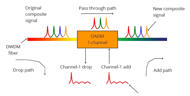
The diagram above demonstrates the operation of a single-channel OADM. This OADM design is used solely to add or drop specific wavelengths of optical signals. From left to right, the input composite signal is divided into two parts: drop and pass-through. The OADM only discards the red optical signal stream. The dropped signal stream is passed to a receiver in the client device. The remaining optical signal from the OADM is combined with the new add signal stream. The OADM adds a new red optical signal stream, operating at the same wavelength as the dropped signal. The new optical signal stream is combined with the pass-through signal to form a new composite signal.
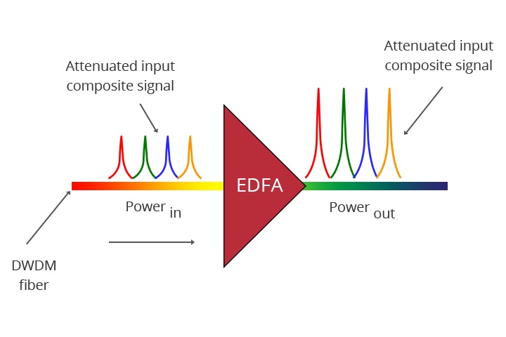
Optical amplifiers enhance the amplitude or gain of optical signals transmitted through the optical fiber by directly stimulating the photons of the signal with additional energy. They are "in-fiber" devices. Optical amplifiers can amplify optical signals of various wavelengths, which is crucial for DWDM system applications.
Wavelength converters in DWDM systems transform an incoming optical signal from one wavelength to another suitable for DWDM applications. Transponders are Optical-Electrical-Optical (OEO) wavelength converters. The transponder performs OEO operations to convert the wavelength of light. In a DWDM system, transponders convert the client optical signal back into an electrical signal (OE), then perform 2R (Re-Amplification, Re-Shaping) or 3R (Re-Amplification, Re-Shaping, Re-Timing) functions.
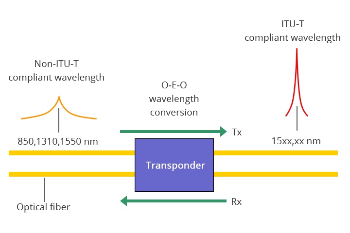
The diagram above depicts the operation of a bidirectional transponder. The transponder is situated between the client device and the DWDM system. From left to right, the transponder receives an optical bitstream operating at a specific wavelength (1310 nm). The transponder converts the operational wavelength of the input bitstream to a wavelength compliant with ITU standards. It transmits its output to the DWDM system. On the receiving side (right to left), the process is reversed. The transponder receives a bitstream compliant with ITU standards and converts the signal back to the wavelength used by the client device.
Elevate your network bandwidth with C-Data's DWDM solution. The C-Data's DWDM, built on cutting-edge DWDM technology, stands out for its high density and capacity. Choose C-Data DWDM to boost the quality of your network and enjoy superior efficiency. Your path to advanced communication starts with quality – choose DWDM for a network that prioritizes performance.
